From Wikipedia's Breadboard article:
A breadboard is a reusable solderless device used to build a (generally temporary) prototype of an electronic circuit and for experimenting with circuit designs.
See Tom Igoe's page on Breadboarding for a thorough introduction.
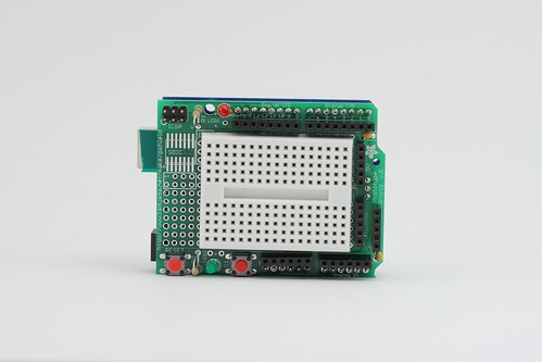
Empty breadboard. Terminals are spaced 0.1" apart - this is a standard size for many electronic components.

Inside the breadboard, horizontal rows of terminals are connected, but only up to the middle divider.
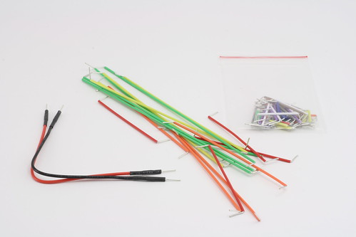
Use wire jumpers to make connections between different rows on the board.

//When placing components like LEDs onto a breadboard, they always have to straddle different rows or the center divider - otherwise, the terminal strip inside the breadboard will connect the different leads of your component, creating a short circuit. To connect components off the board, crimp male header pins on the ends of your cable. See Crimping.
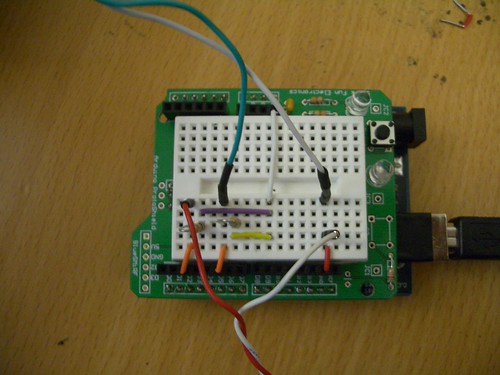
A simple circuit to connect two external switches to two Arduino pins via Pull-up resistors. Note how the resistors straddle two rows.''
The miniature breadboards we are using do not have bus strips for power and ground. Instead, there are short bus headers on one side of the shield holding the breadboard.
Comments (0)
You don't have permission to comment on this page.