Buttons, Switches, LEDs
We'll start our tutorial with three simple light circuits. In the first one, the LED is permanently on. In the second, the LED only lights up when a button is pressed and a circuit is completed. In the third example, we'll replace the manual switch with an Arduino pin (set to output mode), so we can control the LED from our program. Here are three simple circuits to build on your breadboard:
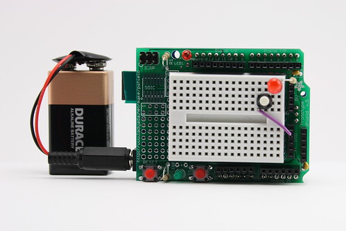
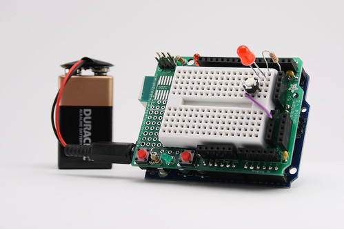
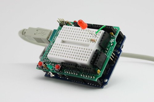
#1: Power an LED from a battery (always on)
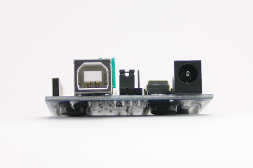
First, take the shield of your Arduino board and set the power jumper to the right, so the board will draw power from the power jack instead of the USB bus:
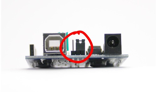
Put the shield back on.
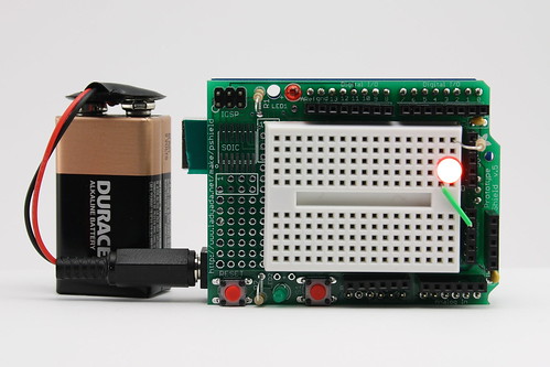
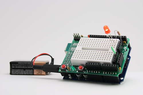
Build the following circuit on your breadboard. Use a 220Ohm resistor (red red brown gold).

Once you have checked it, connect the 9V battery to your board. The LED should light up and stay on. IF it doesn't you probably need to switch the orientation of the LED. The longer lead, the anode, should be connected to the Resistor, the shorter, cathode, to ground.
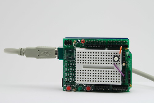
#2: Make a light switch
Next, we'll insert a switch into the circuit. The momentary switches in your kit are "normal open", meaning that the circuit is interrupted in the idle state, when the switch is not pressed. Pressing the switch closes the circuit until you let go agagin.

Optional: If you're ahead, replace the momentary switch with the rocker switch in your kit. or change the circuit so the light is on by default and goes off when you press the momentary switch.
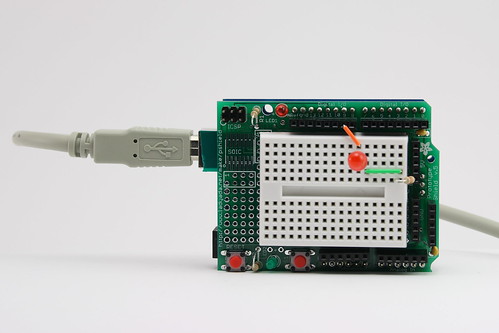
#3: Toggling LED with a mouse button
In the third example, we'll replace the manual switch with an Arduino pin (set to output mode), so we can control the LED from our program. The safe way to do this is to let the Arduino pin sink current - if we toggle the pin low, it acts as ground and current flows through the resistor and the LED as it did in the previous examples. When we take the pin high, to 5V, there is no potential difference and no current flows - the LED stays off.
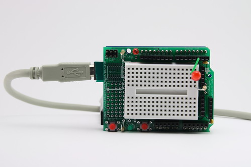
Since we're now communicating with a computer, we can take power from USB. Disconnect the 9V battery. Remove the shield. Move the power jumper to the left, so the board will draw power from USB.
I've chosen to connect to pin 2 in this example. You cannot use pins 0 and 1, since they are also connected to the USB serial port that Arduino uses to communicate to Processing or Flash. You may pick a different pin - you'll have to be dilligent to also reflect that change in the code we use to control the pin.
Here's the breadboarded circuit:
The code for this example is led_control_01.
| Processing: led_control_01.pde |
Flash: led_control_01.fla |
import processing.serial.*;
import cc.arduino.*;
Arduino arduino;
int ledPin = 2;
void setup() {
  size(200, 200);
  arduino = new Arduino(this, Arduino.list()[1], 57600);
  arduino.pinMode(ledPin, Arduino.OUTPUT);
  arduino.digitalWrite(ledPin, Arduino.HIGH);
}
void draw() {
  if (mousePressed == true) {
    arduino.digitalWrite(2,Arduino.LOW);
  } else {
    arduino.digitalWrite(2,Arduino.HIGH);
  }
}
|
import net.eriksjodin.arduino.Arduino;
import net.eriksjodin.arduino.events.ArduinoEvent;
import flash.events.MouseEvent;

var ledPin:Number = 2;

var arduino:Arduino = new Arduino("127.0.0.1", 5331);
arduino.addEventListener(ArduinoEvent.FIRMWARE_VERSION, onArduinoStartup);

function onArduinoStartup(e:ArduinoEvent):void {
	arduino.setPinMode(ledPin, Arduino.OUTPUT);
	arduino.writeDigitalPin(ledPin, Arduino.HIGH);
}

function onMouseClickEvent(event:MouseEvent):void {
	if(event.buttonDown) {
	       arduino.writeDigitalPin(ledPin, Arduino.LOW);
	}else {
	       arduino.writeDigitalPin(ledPin, Arduino.HIGH);
	}
}

stage.addEventListener(MouseEvent.MOUSE_DOWN, onMouseClickEvent);
stage.addEventListener(MouseEvent.MOUSE_UP, onMouseClickEvent);
|
| Note:You'll have to replace the index into Arduino.list()[] with an appropriate setting for your computer. How do you find out what to use? Run the test script you were assigned for homework that prints out a list of serial ports on your computer. On the PC, you'll usually want to use the number listed next to the highest COM port. If that doesn't work, you'll have to find out which COM port the Arduino board is listed as by going to the Device Manager and looking through the port list (Bjoern can demo this). On the mac, look for an entry like this "/dev/tty.usbserial-A1001NTo" and use the index of that entry. |
Note: Your Flash project needs to be an ActionScript 3 project. |
Optional: If you are ahead, change your code so the light stays on when you press the mouse button, and stays off when you press it again. After that, change your code so the light blinks on/off. Then, have the mouse button switch the light between on and blinking.
#4 Sensing buttons in software
We've used code to trigger output - what about the other direction, sensing physical input in code? Just as easy. Here is a simple switch circuit:

When the switch is open, the Arduino pin (set to input mode) is pulled to 5V - in software, we'll read Arduino.HIGH. When the switch is closed, the voltage at the Arduino pin falls to 0V (because the resistance through the switch is essentially 0Ohms - see VoltageDividers) - in software, we'll read Arduino.LOW. The pull-up resistor is used to limit the current going through the circuit. In software, we can check the value of the pin and switch between graphics accordingly.
The corresponding code is in example switch_input_01:
| Processing: switch_input_01.pde |
Flash: switch_input_01.fla |
/*
* background color changes depending on switch state
*/
import processing.serial.*;
import cc.arduino.*;
Arduino arduino;
int switchPin = 2;
void setup() {
size(200, 200);
arduino = new Arduino(this, Arduino.list()[1], 57600);
arduino.pinMode(switchPin, Arduino.INPUT);
}
void draw() {
if(arduino.digitalRead(switchPin)==Arduino.LOW) {
background(255, 0, 0);
} else {
background(0, 0, 0);
}
}
|
import net.eriksjodin.arduino.Arduino;
import net.eriksjodin.arduino.events.ArduinoEvent;
var inputPin:Number = 2;
var arduino:Arduino = new Arduino("127.0.0.1", 5331);
arduino.addEventListener(ArduinoEvent.FIRMWARE_VERSION, onArduinoStartup);
function onArduinoStartup(e:ArduinoEvent):void {
arduino.setPinMode(inputPin, Arduino.INPUT);
arduino.enableDigitalPinReporting();
trace("Arduino initialized.");
}
function onReceiveDigitalData(e:ArduinoEvent):void {
if(e.pin==inputPin) {
if (e.value==Arduino.HIGH) {
circle.visible=false;
} else {
circle.visible=true;
}
}
}
circle.visible=false;
arduino.addEventListener(ArduinoEvent.DIGITAL_DATA, onReceiveDigitalData);
|
| |
Note: Your Flash file needs to have a MovieClip with instance name "circle" on the stage |
#5 Fading LEDs (optional)
What about those "breathing" LEDs on Mac Powerbooks? The fading from bright to dim and back is done using pulse-width modulation (PWM). In essence, the LED is toggled on and off rapidly, say 1000 times a second, faster than your eye can follow. The percentage of time the LED is on (the duty) controls the perceived brightness. To control an LED using PWM, you'll have to connect it to one of the pins that support PWM output - 9, 10 or 11 on the Arduino. Then use the analogWrite(pin,value) command to set duty between 0 and 255. In this example, I've connected the LED to pin 9.
Here is the corresponding code example is led_control_05
| Processing: led_control_05.pde |
Flash: led_control_05.fla |
import processing.serial.*;
import cc.arduino.*;
Arduino arduino;
int pwm=0;
int ledPin=9;
boolean rising=true;
void setup() {
size(200, 200);
arduino = new Arduino(this, Arduino.list()[1], 57600);
arduino.pinMode(ledPin, Arduino.OUTPUT);
arduino.analogWrite(ledPin, pwm);
}
void draw() {
arduino.analogWrite(ledPin, pwm);
println(pwm);
if(rising) {
pwm+=2;
if(pwm>=255) {
rising=false;
}
}
else {
pwm-=2;
if(pwm<=0) {
rising=true;
}
}
}
|
import net.eriksjodin.arduino.Arduino;
import net.eriksjodin.arduino.events.ArduinoEvent;
import flash.events.MouseEvent;
import flash.events.Event;
var ledPin:Number = 9;
var arduino:Arduino = new Arduino("127.0.0.1", 5331);
var pwmValue:Number=0;
var rising:Boolean=true;
var step:Number=10;
arduino.addEventListener(ArduinoEvent.FIRMWARE_VERSION, onArduinoStartup);
function onArduinoStartup(e:ArduinoEvent):void {
arduino.setPinMode(ledPin, Arduino.PWM);
addEventListener(Event.ENTER_FRAME, onEnterFrame);
trace("Arduino initialized.");
}
function onEnterFrame(event:Event):void {
if(rising) {
pwmValue+=step;
if(pwmValue>=254) {
rising=false;
pwmValue=254;
}
} else {
pwmValue-=step;
if(pwmValue<=0) {
rising=true;
pwmValue=0;
}
}
// show current pwmValue value in window
label.text=pwmValue.toString();
// write pwm value to Arduino
arduino.writeAnalogPin(ledPin,pwmValue);
} |
| |
Note: Your Flash file needs to have a TextField with instance name "label" on the stage |
Comments (0)
You don't have permission to comment on this page.